This walkman was very worn and dirty. The belt was totally disintegrated and the clutch gear was cracked. The model is known as WM-B602 in the US and Canada. This player is available in a version with FM radio receiver and is then called WM-BF604 (or WM-AF604 is US/Canada).
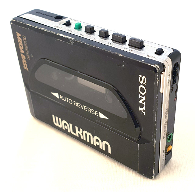
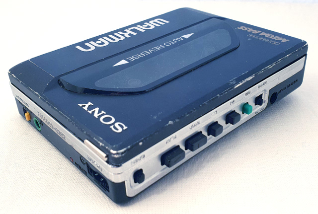
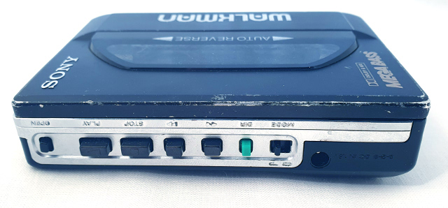
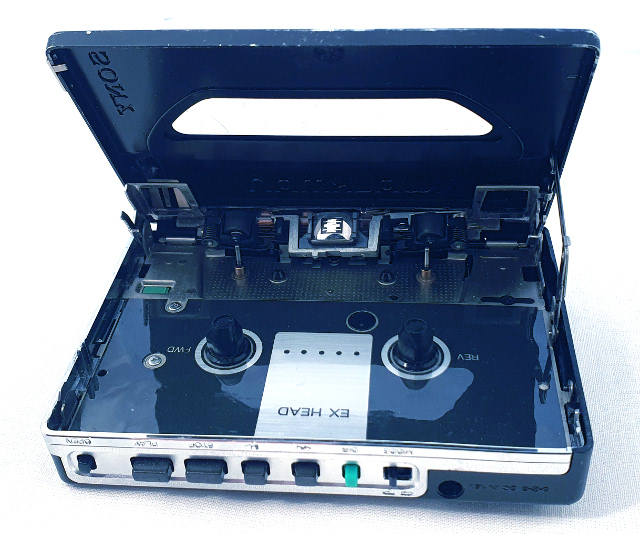
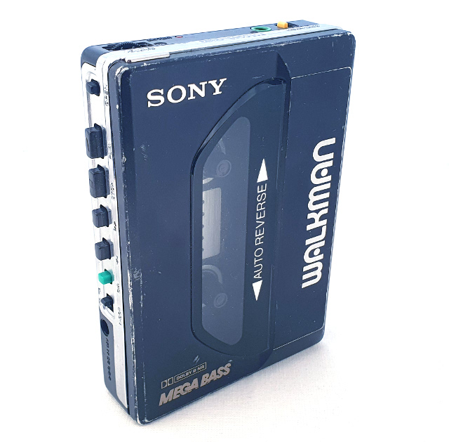
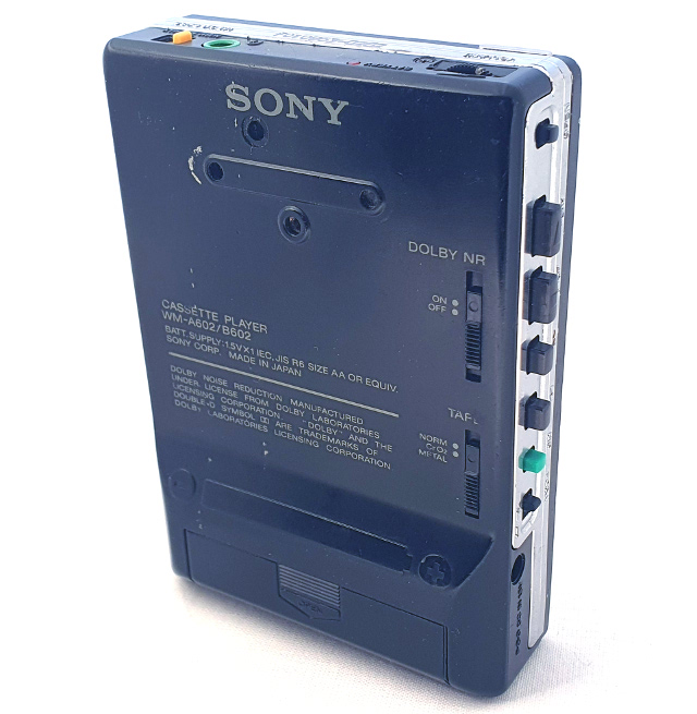 In these pictures I have already cleaned the walkman. It is quite worn and looks anything but brand new - but it works and
I kind of like the worn look.
In these pictures I have already cleaned the walkman. It is quite worn and looks anything but brand new - but it works and
I kind of like the worn look.
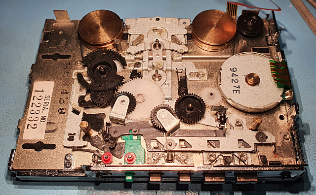 The bottom side of the clutch has a plastic gearwheel that is pressed onto the shaft. In this picture you can see the grey shaft and the new black gearwheel. The original gearwheel was cracked. I ordered a new CNC fabricated one from fixyouraudio.com. The new belt is also from there. I put on some new grease to reduce friction.
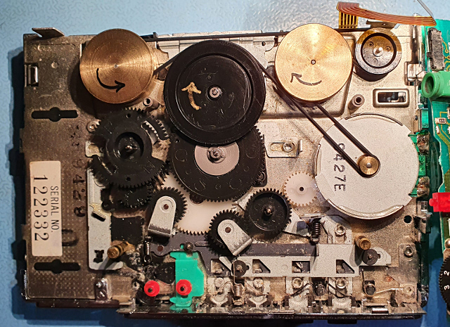
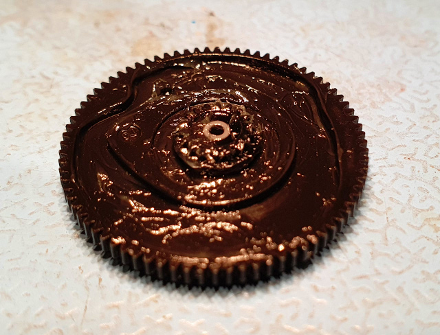 Here the clutch and drive wheel is replaced and a new belt is assembled. The clutch is the one with grey shaft, partly below the drive wheel. The drive wheel is turned by the drive belt and drives the big gear of the clutch. A felt clutch below the grey piece allows some slip while it transfers the torque from the big gear to the smaller gear which turns some other gears and eventually either one of the tape take-up spools. This is a two-way auto-reverse system.
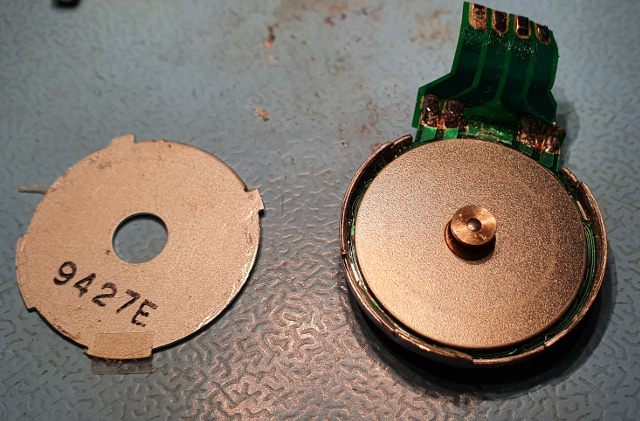
 I also partially opened the motor, which is a brushless 3-pole disc motor with rpm sensing and a constant speed controller. The lid was glued shut, which I peeled open with a surgical knife. I did not manage to remove the rotor to be able to clean and lubricate the bearing, so I let the motor be and glue the lid back on.
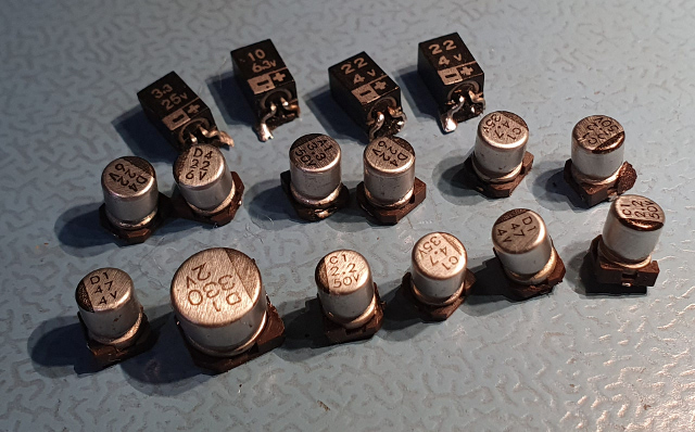 Here are all the electrolytic capacitors replaced:
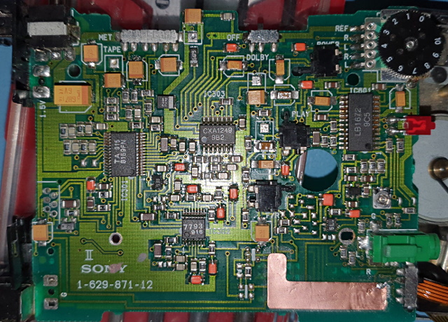 Here is the other side of the circuit board:
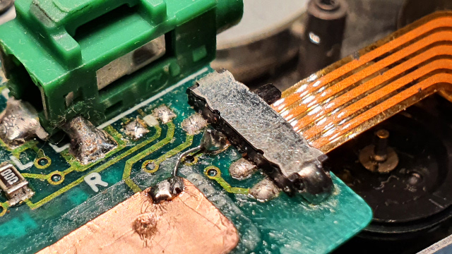
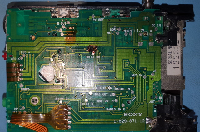 The flex cables were directly soldered to the main circuit board. The desoldering and re-soldering these was not a problem when being extra careful not to peel off the traces from the flex.
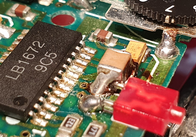 I also soldered a jumper wire to ground from a copper shield that was just floating above the tape head signal traces: